![]()
Guide to Electrical Safety in the Workplace - Overview of NFPA 70E
The continuing modernization of industrial/manufacturing facilities, including significant upgrades to electrical systems, present considerable shock and arc flash hazard exposures to workers. In response, the National Fire Protection Association (NFPA) recently released a 2012 update to standard 70E, Standard for Electrical Safety in the Workplace®, in order to address these and other industry developments.
NFPA 70E was originally developed at the request of the Occupational Safety and Health Administration (OSHA) as an extension of the National Electric Code, in order to help OSHA address the inspection of electrical hazards in the workplace and "provide a practical safe working area for employees relative to the hazards arising from the use of electricity" (NFPA 70E 90.1). The 2012 NFPA 70E update responds to new information about the effects of arc flash, arc blast, and Data Center hazards, as well as recent developments in electrical design and Personal Protective Equipment (PPE). Many industry professionals may not be fully aware either of how the changes in this standard are likely to impact their operations, or of the types of identification and safety solutions available to help them achieve compliance with both old and new elements of NFPA 70E (see Figure 1).
This white paper highlights the changes to the 2012 edition of NFPA 70E, which requires customers to update their compliance to include these latest developments. It also defines the risks associated with arc flash hazards and identifies Panduit solutions available to help prevent arc flash incidents and optimize worker safety. These solutions, based on the Panduit Unified Physical InfrastructureSM (UPI) approach, incorporate identification, labeling, Lockout/Tagout (LOTO), and services offerings to address core power, security, and communications systems and help customers establish compliance with the latest NFPA and OSHA standards.
Figure 1. - 2012 NFPA 70E Standard, which updates safety requirements for the workplace
An arc flash occurs as a result of an electrical fault generating an arc that ionizes the air, leading to combustion. The usual causes of electrical hazards can be mechanical (such as accidental touching, dropping of tools or metal parts, or closing into faulted lines and loose connections) or environmental (such as water, dust, impurities and corrosion at contact surfaces, or failure of insulating materials).
Arc flash is the most common electrical event in the workplace today and the resulting explosion generates the following hazards capable of severe injury or death:
The amount of energy released during an arc flash event depends on three primary factors:
According to Annex K of the NFPA 70E 2012 Edition:
According to NFPA 70E, typically, as much as 80% of hospital admissions from electrical incidents are a result of burns resulting from an arc flash and ignition of flammable clothing rather than electrical shock (see Figure 2). The amount of energy released from an arc flash can be fatal at distances of 10 ft. (3m).
Further-more, more than 2,000 people each year are admitted to burn centers for severe arc flash burns. Estimates also indicate that more than 30,000 non-fatal electrical shock accidents occur each year.

Figure 2. - An arc flash event on an electrical panel in an industrial facility
The purpose of NFPA 70E is to establish an electrically safe workplace by outlining specific practices and standards that must be followed in order to protect the workplace from electrical hazards such as arc flash that can cause injury and death. In order for a work environment to be electrically safe, the energy that workers are exposed to must be minimized while work is being performed. NFPA 70E is the recognized standard that addresses electrical safety requirements for employees. It provides multiple methods by which the employer can calculate or estimate the hazard or risk. It covers electrical safety issues like safety-related work practices, maintenance of electrical equipments/installations, and the requirement of special equipment for electrical installation.
NFPA 70E is a thorough guide toward establishing electrical safety in the workplace by mitigating risk of injury or death. This white paper focuses on regulatory compliance as it relates to work involving electrical hazards, preventive measures, training, and establishing an electrical program as explained in the 2012 edition of the NFPA 70E.
It is important to understand that whether performing energized or de-energized work, mitigating the risk of electrical hazards begins with an analysis to determine the incident energy available at the specific area of work on the electrical power system. The incident energy or hazard category level may be determined utilizing several methods including:
Proper safety precautions must always be taken in all circumstances, whether normal (e.g., working on electrical circuit parts or equipment) or special circumstances (e.g., confined spaces or vision or access to equipment is obstructed).
In most cases, work on electrical equipment greater than or equal to 50 volts AC or 100 volts DC is conducted in a de-energized state using approved Lockout/Tagout (LOTO) procedures, which is the preferred state in which to perform work safely. Energized work is ONLY permitted when the employer can demonstrate that de-energizing introduces additional hazards or is not feasible due to equipment design or operational limitations.
If energized work is absolutely necessary, an Energized Electrical Work Permit must be used. For tasks such as voltage measuring, testing, or troubleshooting, an energized work permit is NOT required. For de-energized work, the conductors are considered to be energized until a tester is used to verify the conductors are de-energized. Therefore, Personal Protective Equipment (PPE) shall be worn by employees until de-energizing verification is complete.
Training is critical for all workers who are exposed to safety hazards. These workers must thoroughly understand the requirements of the electrical safety program, which is required by NFPA 70E and OSHA 29 CFR 1910.147 for all industrial locations and shall include safety principles, controls used to measure and monitor, and specific procedures regarding how to work within the safety boundaries.
Unqualified employee training only includes training on electrical safety practices necessary to avoid injury. Retraining or additional training is required when new technology or job roles change or on an interval NOT to exceed three years. It is important that the employer documents employee training, which shall include the content of the training, employee's name and dates of training.
It is the responsibility of the employer to establish an electrical safety program and training. The employee is responsible for implementing the safety work procedures. In the case of outside contractors, a documented meeting between the host employer and the contractor is required. This meeting should include a discussion of the potential hazards in the workplace and the established safety program.
Annex E of the NFPA 70E standard provides a general outline of recommended topics for an electrical safety program, which shall also provide a procedure for identifying hazards and determining a risk assessment before work is initiated, job briefing methods, and the audit scope and interval. It is specified that an audit of the overall safety program shall be conducted and documented at least every three years.
NFPA 70E specifies Lockout/Tagout (LOTO) procedures as one of several steps involved in establishing a safe working condition. Other key steps identified by NFPA 70E include establishing shock and arc flash approach boundaries for electrical equipment, and clearly identifying hazards with appropriate equipment labeling.
NFPA 70E specifies that LOTO procedures be implemented as part of establishing a safe working condition - see related specification OSHA 29 CFR 1910.147, The Control of Hazardous Energy. Annex G of NFPA 70E has a sample LOTO program that may be used as a template.
A key principle of the LOTO procedure is that a circuit or panel is considered to be "live" until a voltage tester is used to verify the source(s) of energy is removed. Other key principles of a robust LOTO program include:
Employee Involvement - each person who could be exposed to hazardous energy on a specific job is included in the LOTO process - otherwise referred to as Group Lockout. Personnel shift changes shall also be accounted for.
Training - employees are trained on the site specific LOTO/Energy Control Procedure.
Procedures - specific procedures are required for "complex" LOTO instances where there are multiple energy sources and/or multiple crews, locations, employers, specific sequences etc. (see NFPA 70E Article 120 (D) (2) for more information). OSHA 29 CFR 1910.147 (c) (4) (i) requires machine-specific procedures in complex lockout conditions including equipment with more than one energy source (see example in Figure 3).
The LOTO procedures shall contain instructions to include the following:
NOTE: When equipment design does not allow for securing with a lockout device, a Tagout operation may be utilized where a tag is secured to each energy source, clearly communicating the LOTO condition. In a Tagout condition, an additional preventative measure is employed such as removing a fuse, etc.
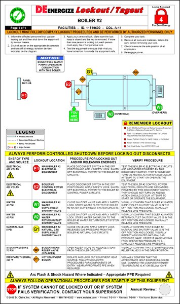
Figure 3. - Example of machine specific LOTO procedures
NOTE: The above machine specific LOTO procedure includes drawings and diagrams to indicate the appropriate equipment being referenced. NFPA 70E requires employers to make these procedures available to all employees.
Device and Tag Requirements - should be robust, unique, and easily identifiable as a lockout device. Other requirements involve a method of including a lock and identification of the LOTO device installer. A circuit breaker is an example of a lock out device that ensures electrical energy sources are isolated for optimal work place safety (see example in Figure 4). Additional requirements are:
_and_a_LOTO_tag_(right).jpg)
Figure 4. - Example of a circuit breaker lockout device (left) and a LOTO tag (right)
Inspections - employer should audit the use of the LOTO procedure at least annually and retrain, improve, etc., as needed.
Shock Hazard Approach Boundaries are requirements developed by the NFPA 70E to minimize the risk of injury to workers as a result of shock and arc flash hazards. These boundaries to energized conductors mitigate the shock hazard. There are three types of Approach Boundaries: Prohibited, Limited, and Restricted. These shock hazard approach boundaries are based on the voltage of the energized equipment and are determined from 70E Table 130.4 (C) (a) for alternating current (AC) systems and Table 130.4 (C) (b) for direct current (DC) voltage systems. Figure 5 is a diagram of this boundary and what type of personnel (qualified or unqualified) is authorized for each specific area.
The arc flash protection boundary is the distance where the incident energy is equal to 5 J/cm2 (1.2 cal/cm2) which is the energy level that unprotected skin will sustain a 2nd degree burn. Therefore PPE is required within the arc flash boundary and unqualified personnel must be continuously escorted by qualified workers. Arc flash PPE is selected from either the incident energy calculation or the hazard risk category determined from NFPA 70E Table 130.7(15).
Observing the arc flash protection boundary can help mitigate the arc flash hazard. This boundary is relevant to systems 50 volts and greater and should be updated when a significant modification or renovation involving the electrical distribution system occurs or it should be reviewed at least every five years. Figure 5 is a diagram of the arc flash protection boundary and what type of personnel (qualified or unqualified) is authorized for each specific area.
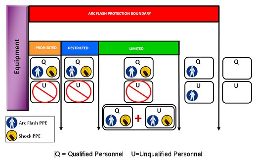
Figure 5. - Prohibited, Restricted and Limited Shock Hazard boundaries and Arc Flash Protection boundaries
The previous edition of the NFPA 70E was the 2009 release where the arc flash labeling requirements addressed only the available incident energy or the required level of PPE. The 2012 edition added several new labeling requirements which are described below.
The NFPA 70E 2012 edition specifies the labeling requirements in section 130.5 (C) for electrical equipment likely to require maintenance and servicing while energized (see example label and sign in Figure 6). The NFPA 2012 70E edition requires that equipment labels applied September 30, 2011 to present contain the following information:
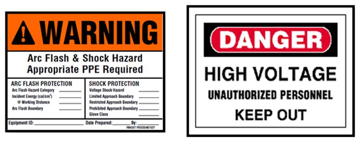
Figure 6. - Example of an arc flash warning label and high voltage safety sign that meet the 2012 NFPA 70E requirements
It is also good practice to include the date of analysis for determining when the next review is required.
NOTE: Labels applied prior to September 30th, 2011 are acceptable if they contain the available incident energy or required level of PPE.
Other alerting techniques such as safety signs, symbols, or prevention tags are recommended to warn employees of potential workplace hazards. As an example of facility signage specified by the National Electric Code - according to 490.53, for equipment operating over 600V, all energized switching and control equipment shall be enclosed in grounded metal cabinets and marked "DANGER - HIGH VOLTAGE - KEEP OUT."
A key strategy for protecting personnel from arc flash is reducing the exposure to electrical hazards by removing the need to enter areas where electrical hazards exist. Door solutions such as data access ports for network connections, infrared sight glass portals, and bulkhead connectors limit the need for entering live cabinets, thereby reducing employee risk.
Trending recently is the dangerous option to install network equipment like Ethernet switches in control and power panels, where there can be an increased hazard risk for service and configuration. Zone architecture solutions that provide separate zone enclosures to house networking assets can physically remove the hazard of exposure to higher energy circuits.
Personal Protective Equipment (PPE) includes specialized clothing or equipment worn by employees to protect the body including the head, face, eyes, and hands. The level of PPE is determined by the degree of the shock and arc flash hazard. The Hazard Risk Category determined by the NFPA 70E 130.7(C) (15) or the incident energy calculation is then used to decide the required PPE for the task. For example, the Hazard Risk Category for toggling a circuit breaker with the enclosure doors open for a 600V class motor control center (MCCs) is a Hazard/Risk Category (HRC) 1 according to Table 130.7 (C) (15) (a). According to Table 130.7 (C) (16), for HRC 1, the PPE required is a hard hat, safety glasses or goggles, hearing protection, heavy duty leather gloves, and leather work shoes. Additionally, insulated tools and equipment (and/or handling equipment) are used when working within the limited approach boundary.
The PPE is listed in Table 130.7 (C) (16) by Hazard Risk Categories 0 through 4. Above 40 cal/cm2 is considered HRC DANGEROUS because PPE is not able to sufficiently protect employees, which means energized work is prohibited. NFPA 70E Table 130.7 (C) (14) lists the standards relevant to protective equipment. Personal Protective Equipment and Hazard Risk Categories are defined in Table 1.
Table 1. - Personal Protective Equipment and Hazard Risk Categories
| Categories | Arc Rated (AR) Clothing | Protective Equipment | Shock Protection |
|---|---|---|---|
| Category 0 0-1.2cal/cm2 Category 0 clothing does not have to meet Arc Rating Requirement |
|
|
|
| Category 1 1.2-4cal/cm2 |
|
|
|
| Category 2 4-8 cal/cm2 |
|
|
|
| Category 3 8-25 cal/cm2 Category 3 Arc Rated (AR) clothing must have a system AR=25cal/cm2 |
|
|
|
| Category 4 25-40 cal/cm2 Category 4 Arc Rated (AR) clothing must have a system AR=40cal/cm2 |
|
|
|
Source: NFPA 70E, Electrical Safety in the Workplace, 2012 edition.
Panduit offers a safety solution to our customers consisting of relevant products and services to help mitigate risk created by hazards in the workplace. We provide the entire system of reliable solutions, and ongoing support needed for our customers to comply with regulatory standards and assist with the safety of employees and property that are exposed to hazardous energy.
Panduit's safety solution is a single point of contact for the protection of people and infrastructures from the hazards energized equipment and systems present, encompassing the breadth and depth of the following solution categories:
Panduit provides a large span of identification solutions for indoor and outdoor/harsh environments including pre-printed, print on demand (do-it-yourself) software/printer systems, or custom printed solutions:

Figure 8. - Example of safety and facilities labeling - Panduit TDP43ME Thermal Transfer Desktop Printer producing an arc flash label
Panduit has a large range of secure and compliant lockout devices for electrical and other types of hazardous energy such as:
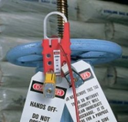
Figure 9. - Equipment being locked out using Panduit Multiple Lockout Device PSL-MLD
Panduit Multiple Lockout Device PSL-MLD can be used alone as a lockout hasp, or with the provided cable to lockout electrical disconnects, gate valves, or large cumbersome devices.
A key element of an arc flash program is to remove/reduce the need for employees to be exposed to arc flash and electrical shock hazards. The goal is to eliminate the hazard rather than require personnel to wear PPE against an existing threat. Network switches and Ethernet connections should not be located inside control panels without protective barriers where arc flash and electric shock hazards exist. For situations where network switches and connections are positioned in-panel, solutions are available that allow employees to safely access networks without entering control enclosures or being exposed to hazardous voltages.
Panduit provides a range of safety solutions for various levels of the network:
_and_Panduit_Industrial_Zone_Enclosure_(right).jpg)
Figure 10. - Panduit IndustrialNet Data Access Port (left) and Panduit Industrial Zone Enclosure (right)
The Panduit IndustrialNetTM Data Access Port (Figure 10 - left) promotes electrical safety by limiting the need to open the electrical panel.
The Physical barriers inside enclosures such as the new Panduit Industrial Zone Enclosure (Figure 10 - right) decrease electrical hazard.
Panduit has a series of value-added tools and templates available for training and safety program implementations that include:
Mitigating workplace hazards and protecting employees is critical to maintaining a successful and growing operation. This is a challenge considering the continual release of new technologies into the market and the internal changes taking place within most facilities. As a result, the complexity of the supporting power systems and demand for electrical power are increasing.
This paper explains the ways that NFPA 70E has evolved to address the technology/market trends and further mitigate electrical hazards in the workplace. Unfortunately, it is estimated that only 20% of the industrial sector is compliant to the required elements within the NFPA 70E. Over the next five years, it is expected that the percentage of compliant facilities will climb as the industry becomes more aware of the severity of the arc flash hazard and effective methods to mitigate this risk. Implementing electrical safety programs as outlined in NFPA 70E will benefit both the employee and employer, resulting in a safer and an overall lower cost operation.
For further information, please visit www.panduit.com/safety or contact your distributor for more information.
The information contained herein is intended as a guide for use by persons having technical skill at their own discretion and risk. Panduit disclaims any liability arising from any information contained herein or for the absence of same.
Panduit is a world-class developer and provider of leading-edge solutions that help customers optimize the physical infrastructure through simplification, increased agility and operational efficiency. Panduit's Unified Physical InfrastructureSM (UPI) based solutions give enterprises the capabilities to connect, manage and automate communications, computing, power, control and security systems for a smarter, unified business foundation. Panduit provides flexible, end-to-end solutions tailored by application and industry to drive performance, operational and financial advantages. Panduit's global manufacturing, logistics, and e-commerce capabilities along with a global network of distribution partners help customers reduce supply chain risk. Strong technology relationships with industry leading systems vendors and an engaged partner ecosystem of consultants, integrators and contractors together with its global staff and unmatched service and support make Panduit a valuable and trusted partner.
©2012 Panduit Corp. All rights reserved.
Title: Arc Flash and Electrical Safety
URL: http://www.deenergize.com/?target=Arc_Flash_and_Electrical_Safety
Printed: Friday July 17th, 2026
Copyright © 2026 St. Claire, Inc.
DEenergize is a trademark of St. Claire, Inc.